Contents
- Introduction
- Log entires for 2013
- Log entires for January-March 2014
- Log entires for April-June 2014
- Log entires for July-December 2014
- Log entries for January-February 2015
- Log entries for March-June 2015
- Log entries for July 2015-December 2016
- Log entries for 2017
- Log entries for 2018
- Mar 19, 2019, Reverse Engineer G007 Sense Amplifier
- May 17, 2019, Reassemble TTY, fix G007 diode
- June 4, 2019, Get BRPE punch, straighten door trim
- June 6, 2019, Retrocomputer Museum Exhibit
- Most recent log entries
This is a chronological log of the progress restoring
the University of Iowa's PDP-8 computer.
Entries are added at the end as work progresses. Click on any thumbnail
image to see full-sized image.
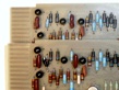
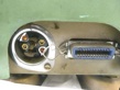
Bug 64:
We reverse engineered the G007 sense amplifier board, on the theory
(advanced in the log entry for
Dec 6, 2018)
that one of these boards might be pulling the Memory Strobe signal to ground.
The parts are labeled with the part numbers given in the
G007 schematic
in ght Feb. 1966 edition of the maintenance manual. Our board is a G007C,
while the board in the manual is a G007D.
The difference between these
outlined in the reverse engineered board with an orange square outlining
a DEC D664 diode that was later replaced by R29 in Rev D.
This does not agree with the
G007C schematic.
on Vince Slyngstad's web site, where a resistor is also shown. Evidently,
DEC experimented with different parts while continuing to use the same
revision of the board etch.
|
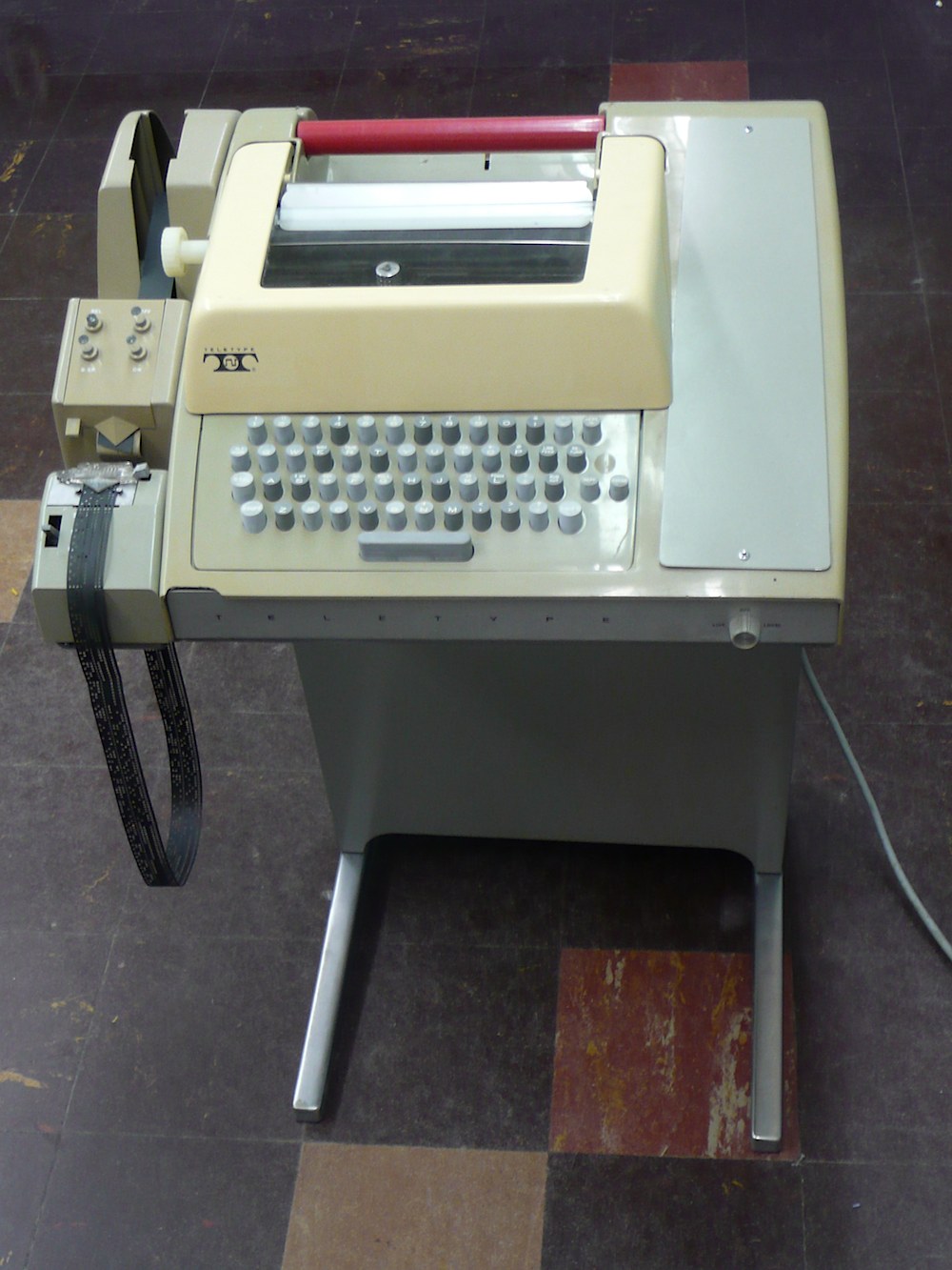
| The Teletype
|
|---|
Bug 26:
In preparation for the University of Iowa Tech Forum on June 6,
where artifacts from the Retrocomputer Lab will be on exhibit,
we put the cover on the Teletype for the first time since we
began work on it. Looks good!
|
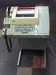
| Bad diode replaced
|
|---|
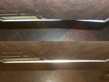
Bug 64:
We used an ohm meter to check all the diodes on the G107 sense-amplifier boards,
and found one of them that was bad, measuring as an open circuit in both
directions. The diode in question was D15 on the
G007 schematic
in the Maintenance Manual.
DEC's part number for this diode is D668, and their
semiconductor substitution
instructions in the Maintenance Manual (Table 10-1, page 10-5)
say to use two D-664 (1N3606) diodes in series.
As can be seen in the photo, showing the repaired board (bottom) and a board
with a good diode (top), the pair of diodes in series is a bit bulky. We
painted the transparent glass body of the diode with black paint because the
forward frop of this diode is used as a voltage regulator, and the forward
drop of glass-encased silicon diodes is notoriously light sensitive.
|
|
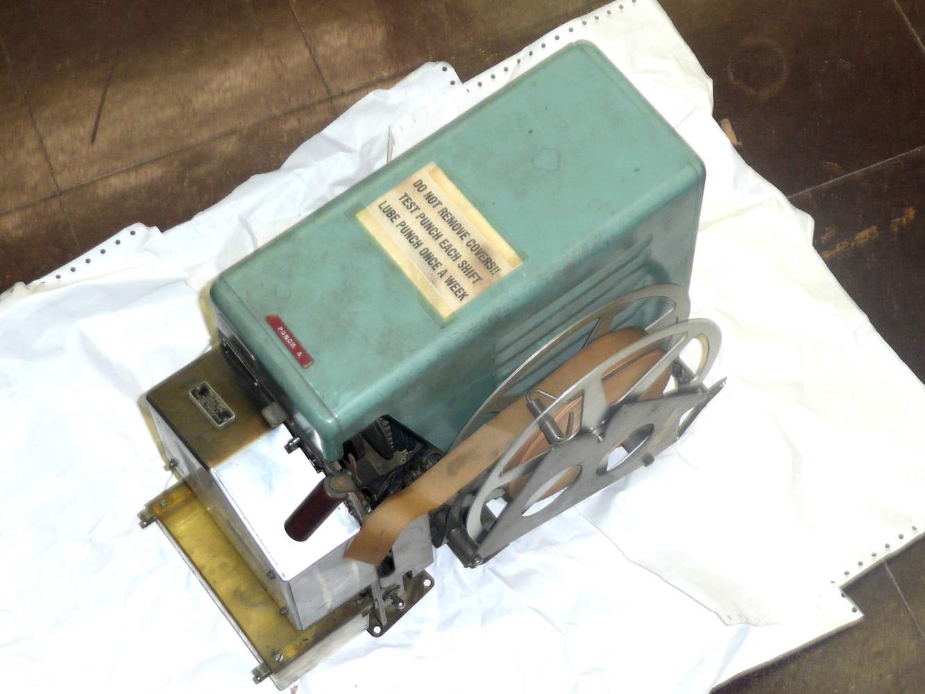
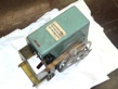
| The BRPE punch
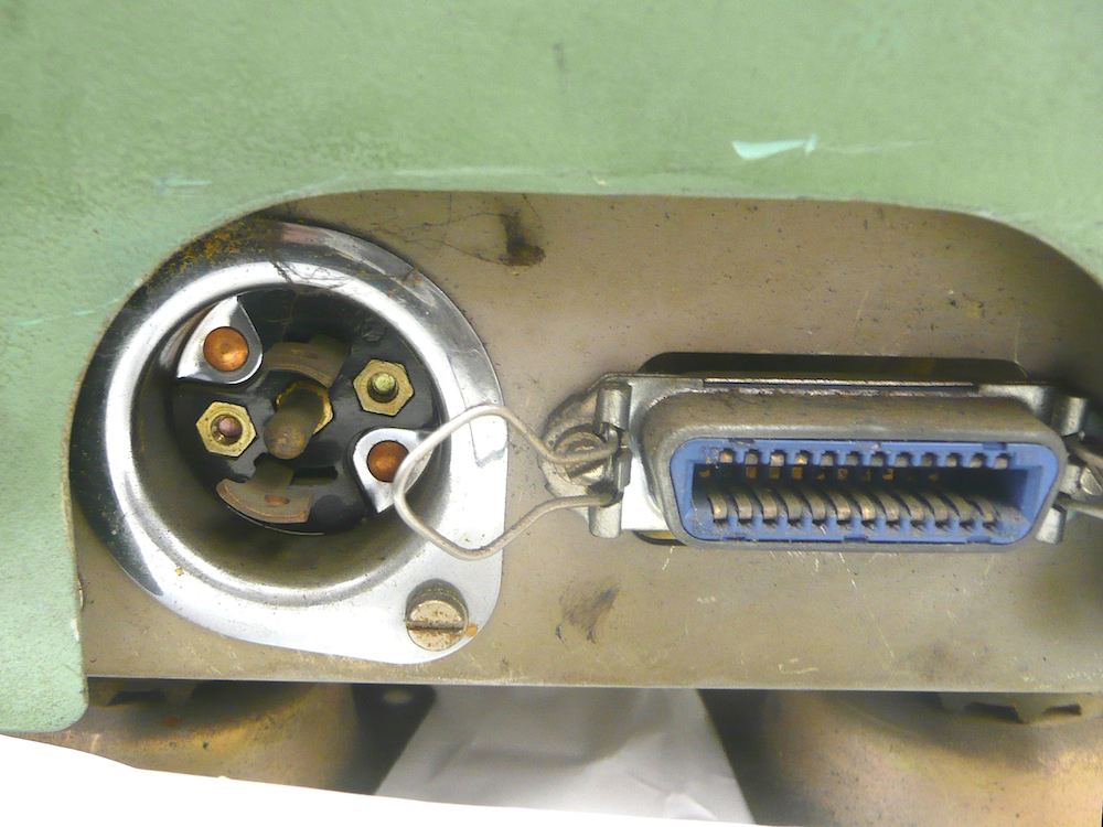
| Problem plugs
|
|---|
When we recovered the PDP-8 from its brief stay at university surplus, we did
not get the high-speed paper-tape punch that the psychology department had used
with the machine. That was apparently a Tally punch, while the
PDP-8 Users Handbook (page 64, 1966 edition) says that DEC supported
Teletype's BRPE reader. When a pair of old BRPE readers became available,
we got them. The machines were used by Jackson Typesetting,
in Jackson, Michigan, acquired through Dan Foust.
These machines pose some problems, because they are configured for 7/8-inch
paper tape, suitable for punching with 6-bit codes, but with two punches, there
is hope that we can combine parts from two punches to make one punch that
works with 1-inch tape and 8-bits per character.
A second problem is finding the plugs to connect to the machine. The 3-pin
twist-lock connector for power may be harder to source than the 24-conductor
ribbon
connector
since this is mechanically (but not electrically) identical to what later
came to be known as a Centronics connector.
BRPE, is an example of a naming scheme Teletype corporation used.
The root, RP, stands for reperforator, because any punch that was
electrically driven was assumed to be creating a duplicate of a paper tape
that had been originally perforated elsewhere and then read.
The final E seems to have been used on all high-speed punches, perhaps
indicating an electrical interface.
The first letter was assigned sequentially; according to
Nick England, the first in the series was the ARPE a magnet controlled
reperforator. The CRPE may not have made it to market, but Jim Haynes
says that there was a DRPE tuned reed punch.
|
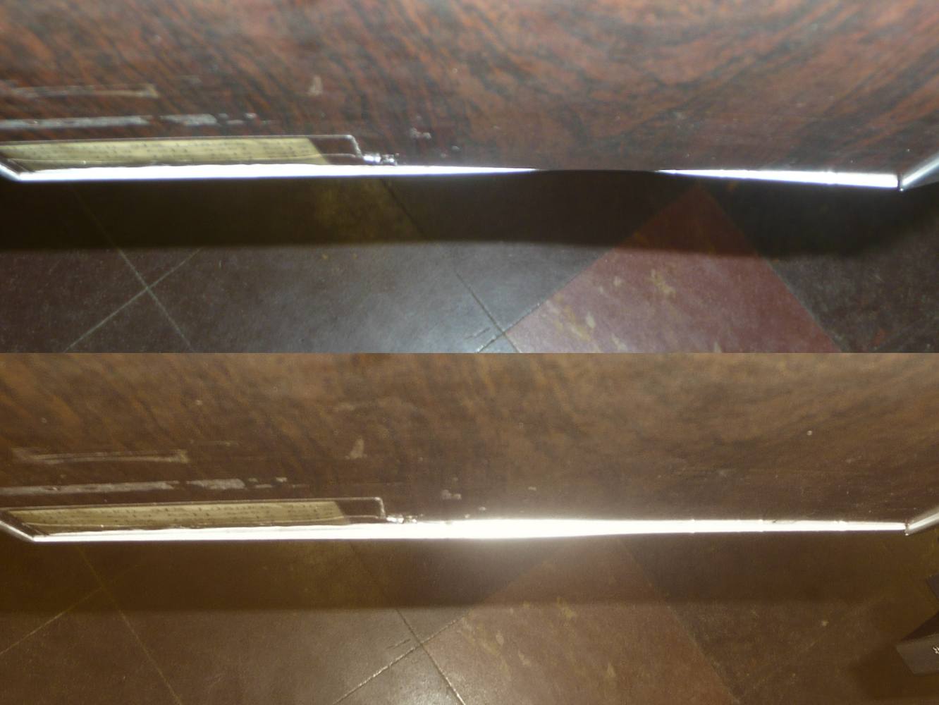
Door trim
before and after
|
|---|
In preparing to exhibit the PDP-8 at the University of Iowa Tech Forum,
we noticed that the bottom trim strip on the left front door of the PDP-8
was bent. Removing the door and banging on the back of the trim strip
was sufficient to largely remove the bend, but after doing this,
it was clear that whatever had bent the trim also bent the metal door panel
itself. We left that alone for the time being. In the before and after
photo to the right, the slight bend in the door panel is only apparent after
the trim strip was straightened, and only when viewed looking down
from an extreme angle.
|
|
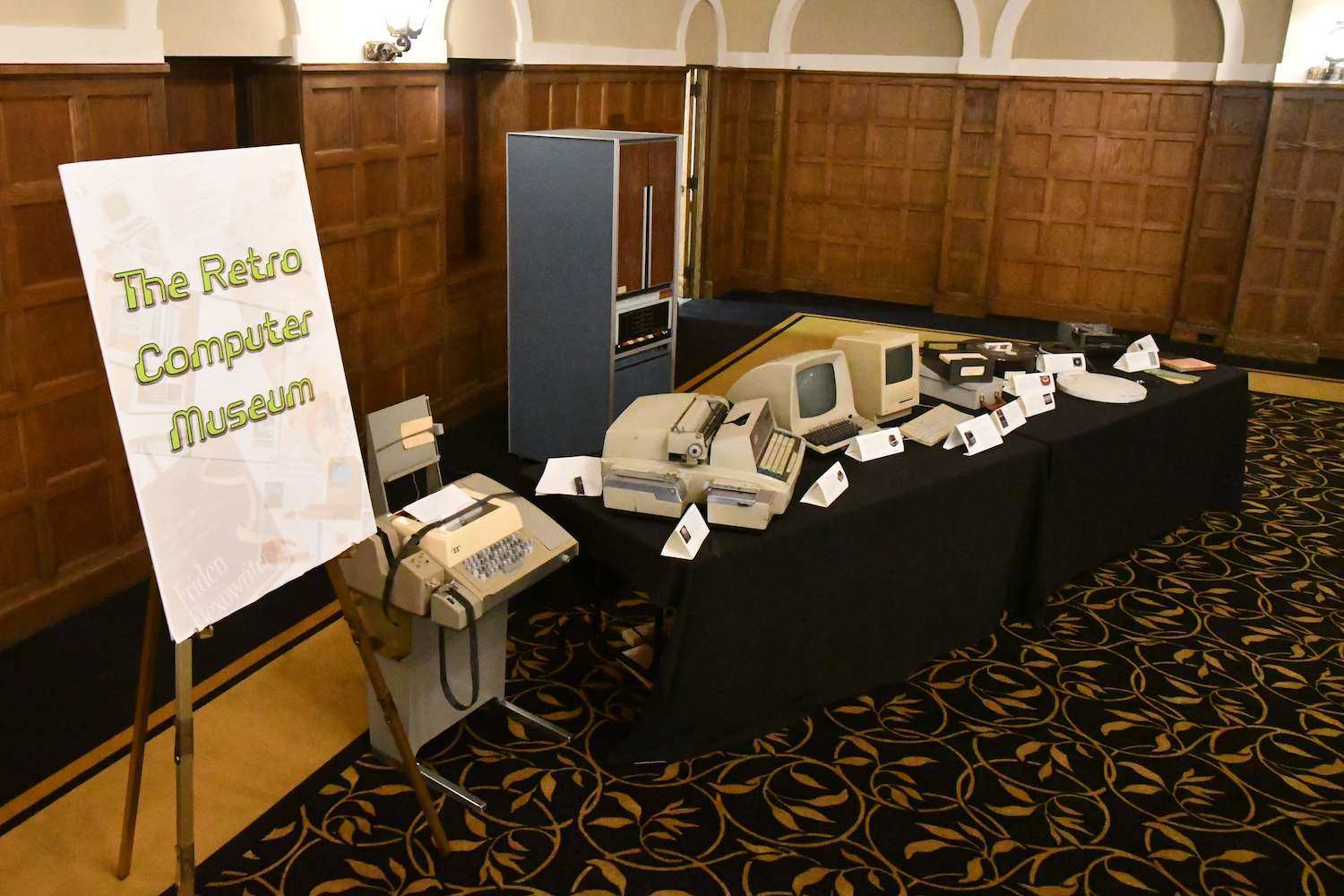
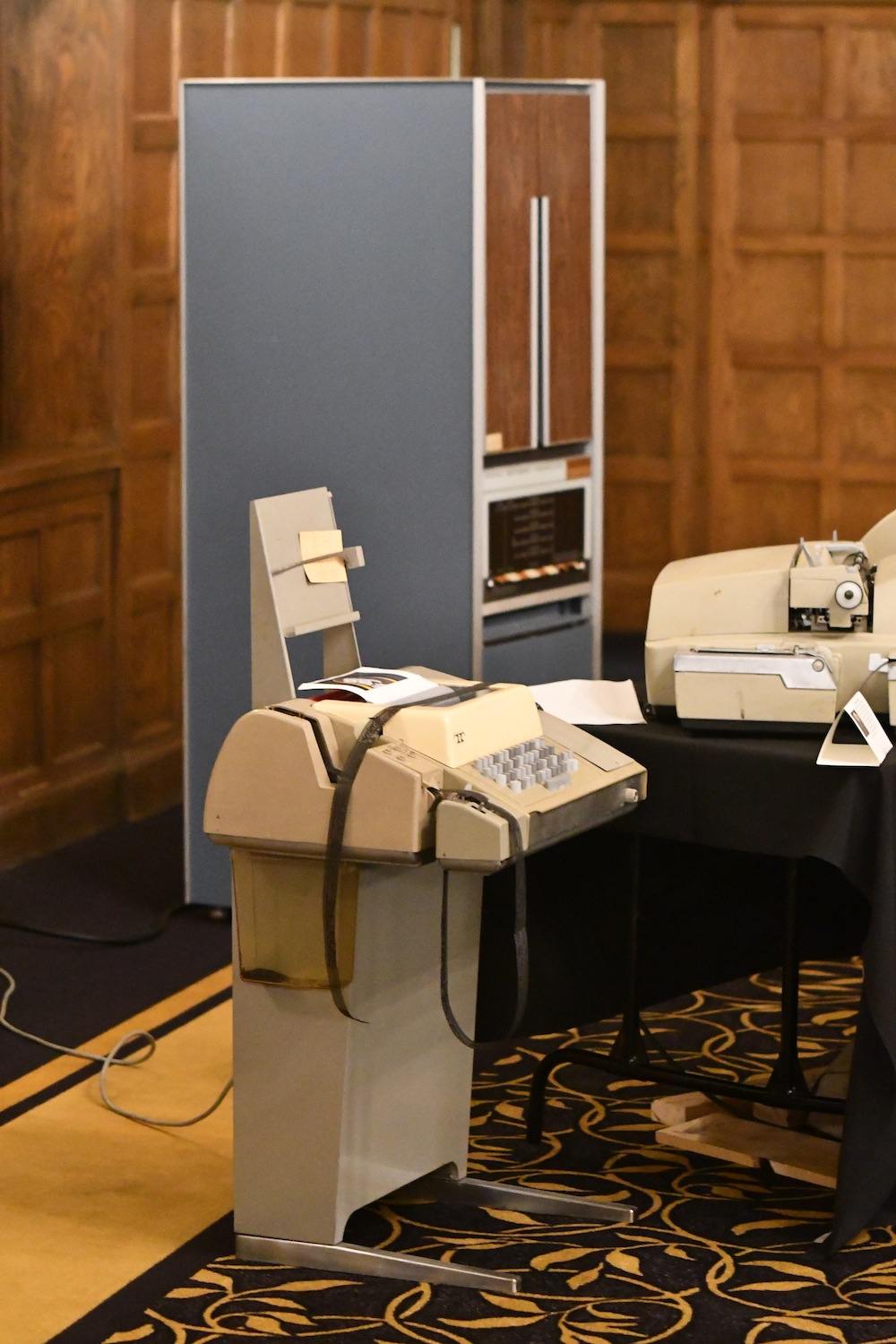
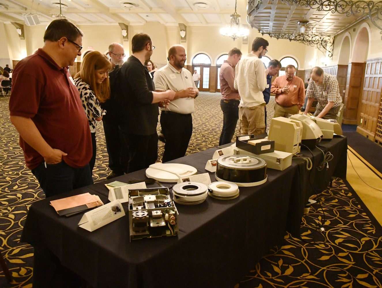
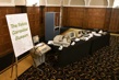
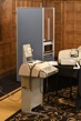
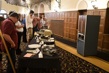
| The exhibit
|
|---|
|
|
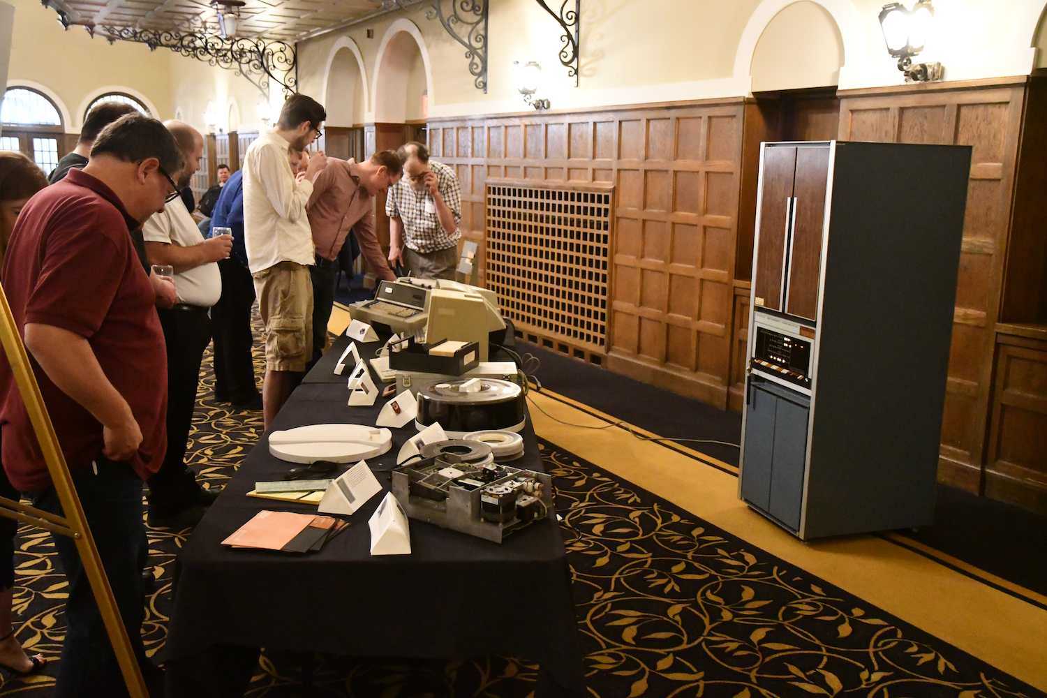
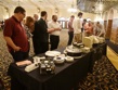
| An appreciative audience
|
|---|
|
photos ©2019 Michael J. Jenn, U. of Iowa ITS-Enterprise Services
|
The whole point of restoring old computer equipment is to educate, so when
the organizers of the
University of Iowa Tech Forum
asked if we had anything worth exhibiting, I volunteered.
Later, as it turned out, we were asked to abandon the space in the old
Communications Center (the former home of the School of Journalism),
so we ended up coordinating the move out of the old
space into new space in Jessup Hall with the Tech Forum. We exhibited
The PDP-8
The Teletype Model 33 ASR
The Flexowriter
An ADM-5a dumb terminal
An Apple Mac/SE
Two files of punched cards (capacity 1000 and 2000 cards)
An IBM 2314 (style) disk pack (20 surfaces)
A DEC RK05 (style) disk pack (2 surfaces)
A stack of 9-track tapes
An IBM 8-inch floppy disk drive and floppy disks
The exhibit was very well received. We left the Teletype turned on with
the paper-tape punch on so that people could type (and punch) souveniers,
and we left the PDP-8 on and running (unfortunately, with all memory reading
as zero, the program was just a sequence of AND instructions.)