
The Friden FlexowriterA Guided Tour
Part of
the Flexowriter pages
|
The Friden FlexowriterA Guided Tour
Part of
the Flexowriter pages
|
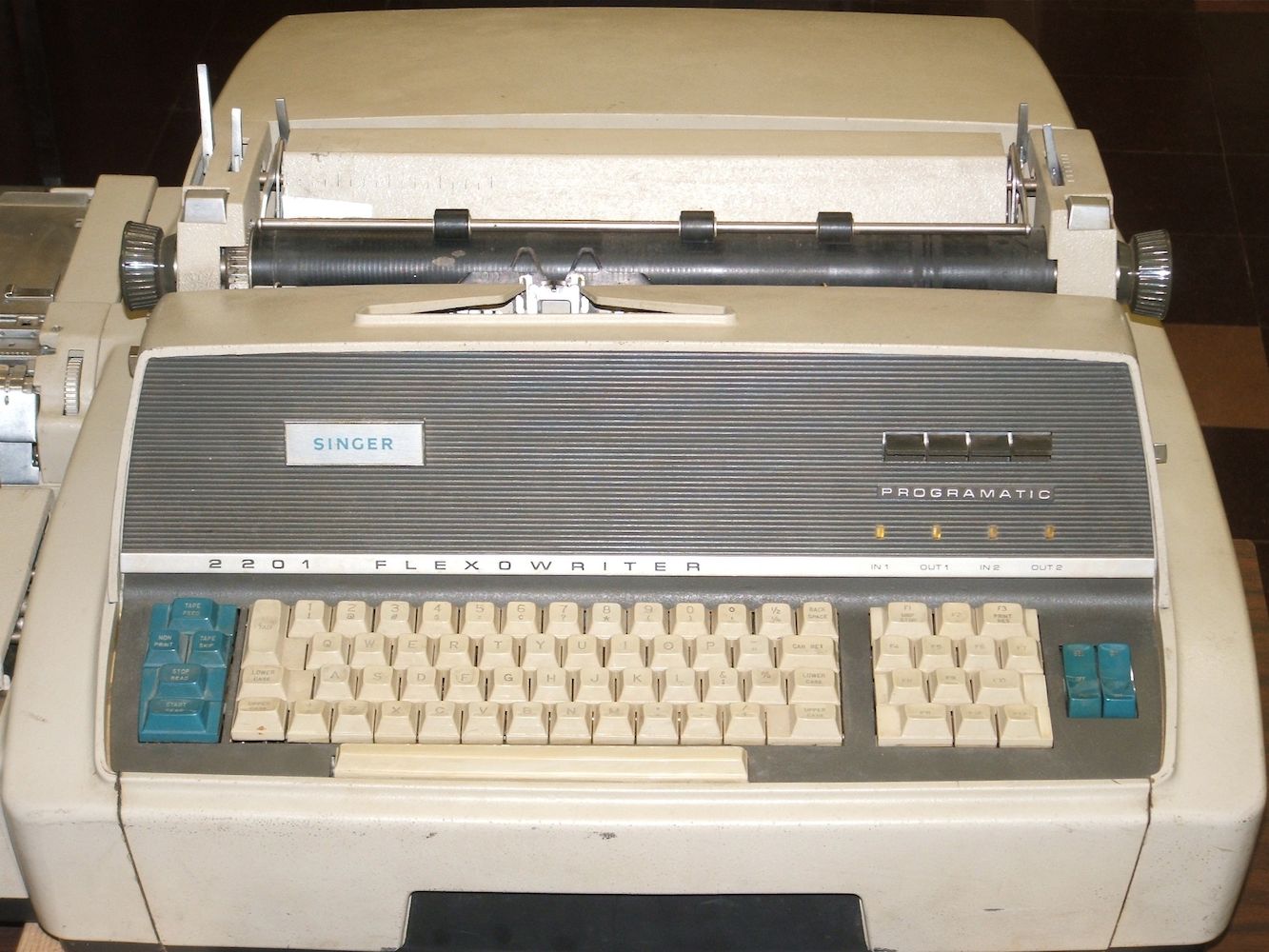
What follows is an inventory that can also serve as a guided tour through the
parts of the Friden Flexowriter system we have, originally manufactured in the
mid 1960s. Click on any of the thumbnail photos for a larger view.
|
|
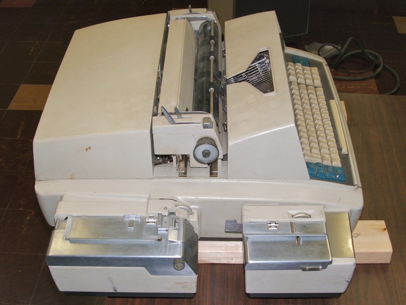
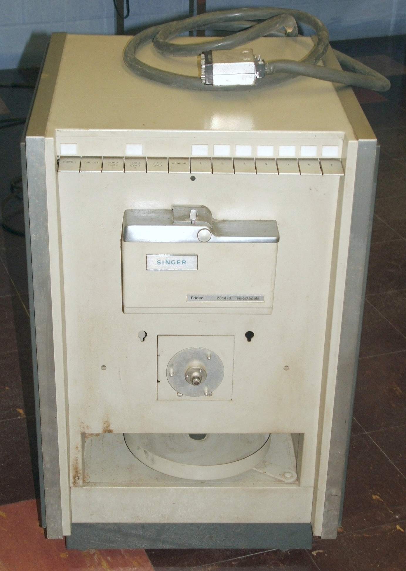
| Front and side views | |
|---|---|
The Flexowriter is designed to balance on its rear end for easy access to its
underside. When we tipped our machine onto its rear, we found that only two
of the rubber feet were intact. One was missing and one was only half there.
We therefore set to work to
make replacements.
|
|
|
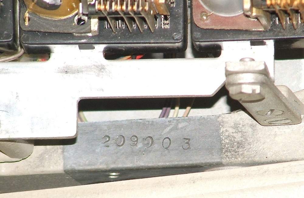
| The nameplate and serial number | |
|---|---|
In broad outline, the mechanism of the Flexowriter conforms to these US patents, which have many shared illustrations:
-- 2700445 Type Action for Typewriters, Edwin Blodgett, 1955.
-- 2797788 Carriage Return Mechanism for Typewriters, Edwin Blodgett, 1957.
-- 2905298 Writing Machine, Edwin Blodgett, 1959.
The Friden 2201 was priced at £2,900 in 1969, according to the British Commercial Computer Digest. The dimensions given there, 5 by 3 feet, must include the table we do not have.
The Computer History Museum has a Model 2301, a Model 2301-A and a Model 2303 Flexowriter. At first glance, these look identical to the machine described here, but the machine we have has an array of programmable function keys between the keyboard and the power switches on the right, where none of the museum's machines have this feature.
The
inventory
of the
University of Amsterdam Computer Museum
lists a Friden 2201; a photo is attached to the inventory entry. Judging by
the photo, it appears to be in good condition.
|
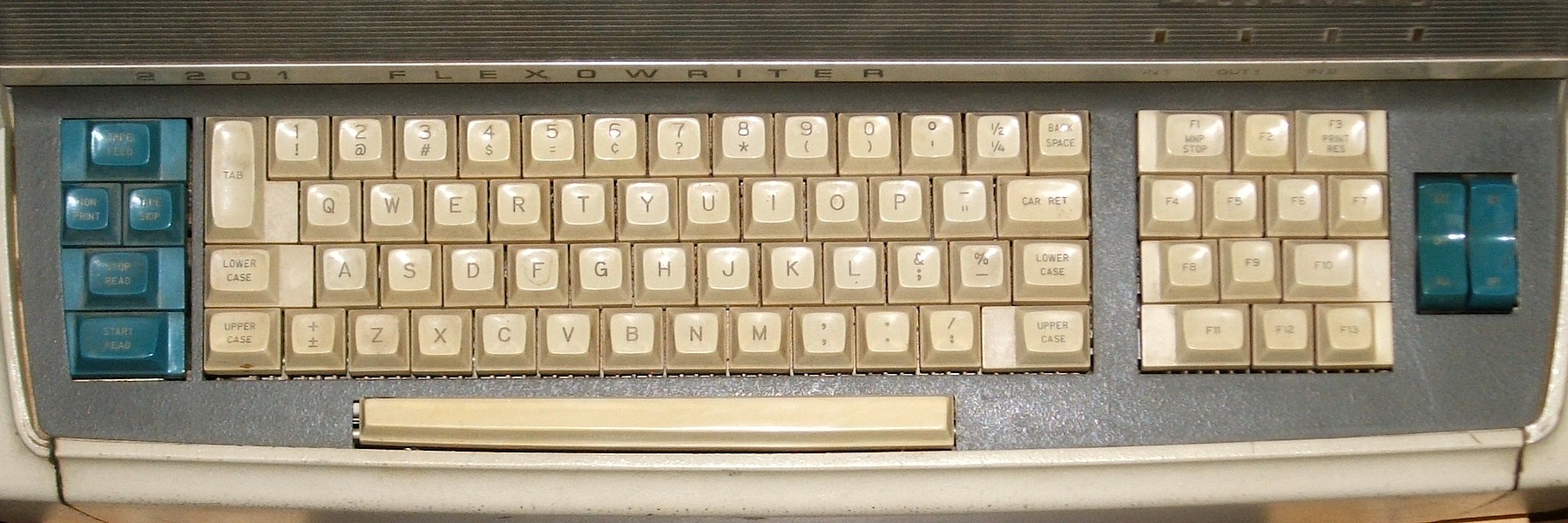
| The Keyboard |
|---|
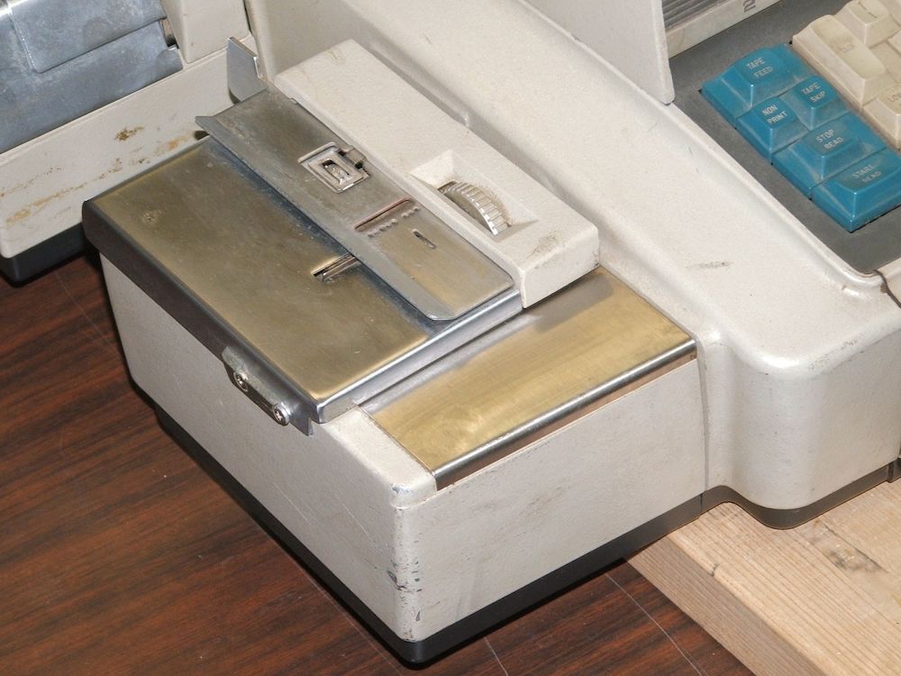
A second set of function keys on the left side of the keyboard have fixed functions related to the paper-tape punch and reader. The keys labeled START READ and STOP READ start and stop the reader, while the TAPE FEED key causes the paper-tape punch to punch leader (a series of ignored character codes). NON PRINT is used to turn off printing, so that, for example, binary tape can be duplicated. TAPE SKIP causes content on the tape reader to be skipped until a control character is encountered that causes normal function to resume.
Finally, the numeric row of the keyboard has the numerals in the shifted
position and the punctuation marks in the un-shifted position, the reverse of
most typewriters as well as the reverse of most computer terminals. Note that
the punctuation marks aren't exactly the ones yu would expect on a modern
computer keyboard, although many of them are on the keys where you would expect
them.
The print mechanism is an entirely conventional type basket, fixed to the main chassis, working against a paper carriage that moves left and write as the typing progresses.
|
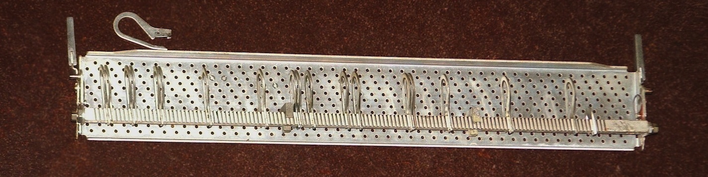
| The tab rack |
|---|
|
|
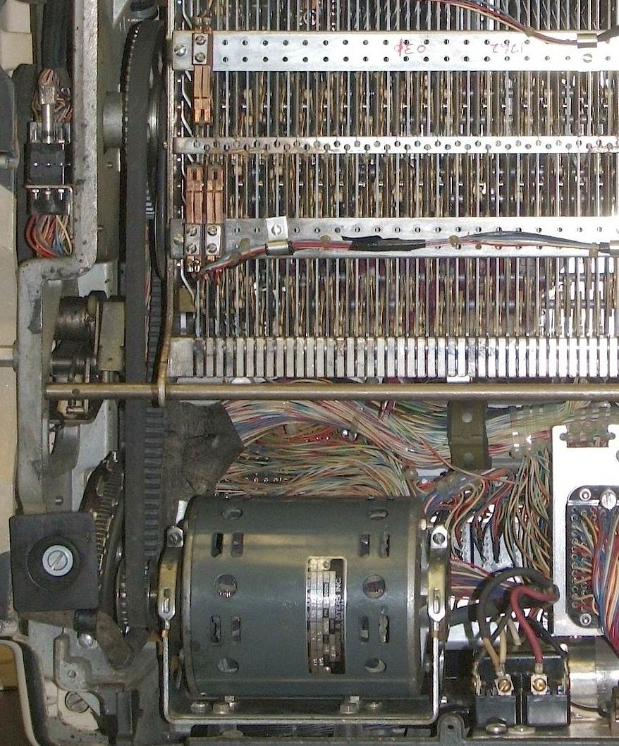
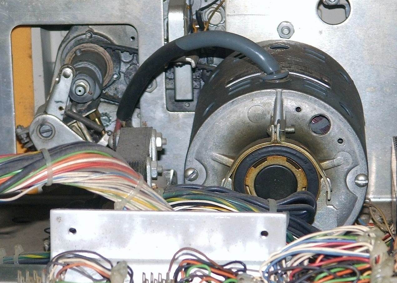
| The motor and drive roller | |
|---|---|
One of the driven elements, under the keyboard, is the drive roller. This rubber roller crosses the width of the keyboard. When you press a key, this engages a cam against the drive roller. The rotating roller grabs the cam, giving a solid yank to the key and powering not only the typing mechanism but also the keyboard encoding matrix.
The relationship between drive rollers, cams and type-bars in our Flexowriter is clearly documented described in this patent:
-- 3355000 Type bar actuating mechanism with separate drive and actuating bell cranks, Edwin O. Blodgett, 1967.
|
|
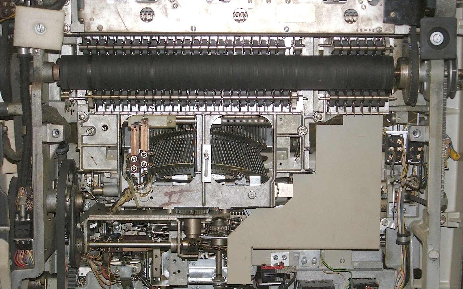
| The code selector | |
|---|---|
The entire code selector or encoder matrix is mounted on hinges. With the Flexowriter tipped up onto its back side, loosening two jack screws allows the entire encoder, including its black plexiglass bottom cover, to swing out and down exposing the power roller and the underside of the typing mechanism. The jack screws have conical bases in order to precisely align the code selector slides with the keyboard when the matrix is in its operating position.
The encoder mechanism of our Flexowriter corresponds very closely to that described in this patent:
-- 3269509 Easily removable and adjustable code selector linkage means, Henry E. Smith, 1966.
| |
|
|
| The paper-tape punch | |
|---|---|
| |
|
|
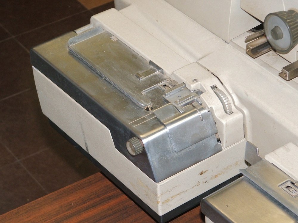
| The paper-tape reader | |
|---|---|
Unlike most paper-tape readers, this one has two drive sprockets, one ahead of the read mechanism, one behind it, linked by a large spur gear on the side of the reader. This allows this reader to reliably feed edge-punched cards, a data recording medium unique to the Flexowriter. Without the second sprocket, the cards could easily be pulled out of alignment during reading.
While the mounting of the paper-tape and edge-punched card reader differs from that shown in the patent drawings, the reader appears to conform to the design shown here:
-- 2945623 Tape and Card Record Media Reader, Edwin Blodgett, 1960.
|
|
| Opening the rear cover | |
|---|---|
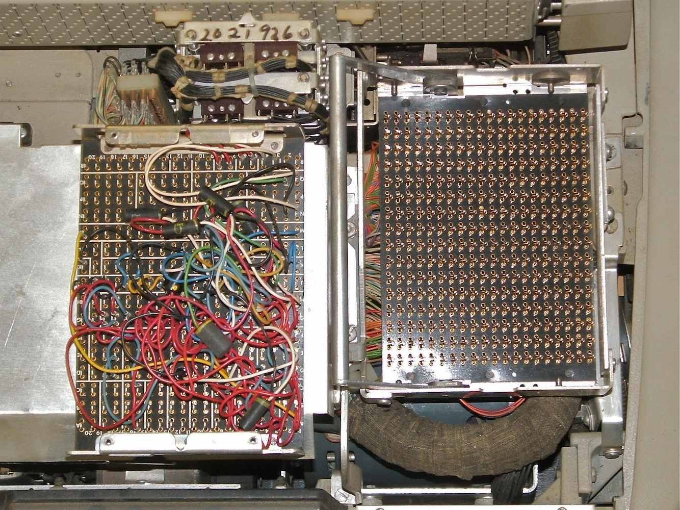
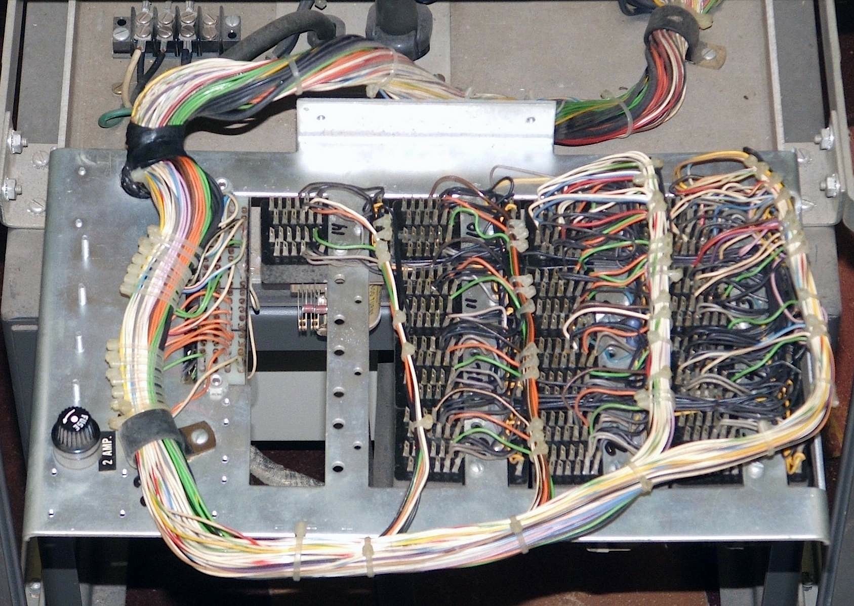
A securely covered plugboard is locked into a large socket beside the relays. The locking lever for the plugboard operates a pair of cams that both align the plugboard in its socket and press it sideways with enough force to guarantee a secure connection. The plugboard mechanism appears to operate as described in this US patent:
-- 3202878 Plugboard Apparatus with Lateral Movement Conneccting Means, Mel Kinney and Donald Rolph, 1961.
|
|
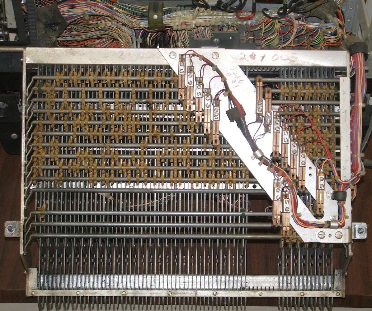
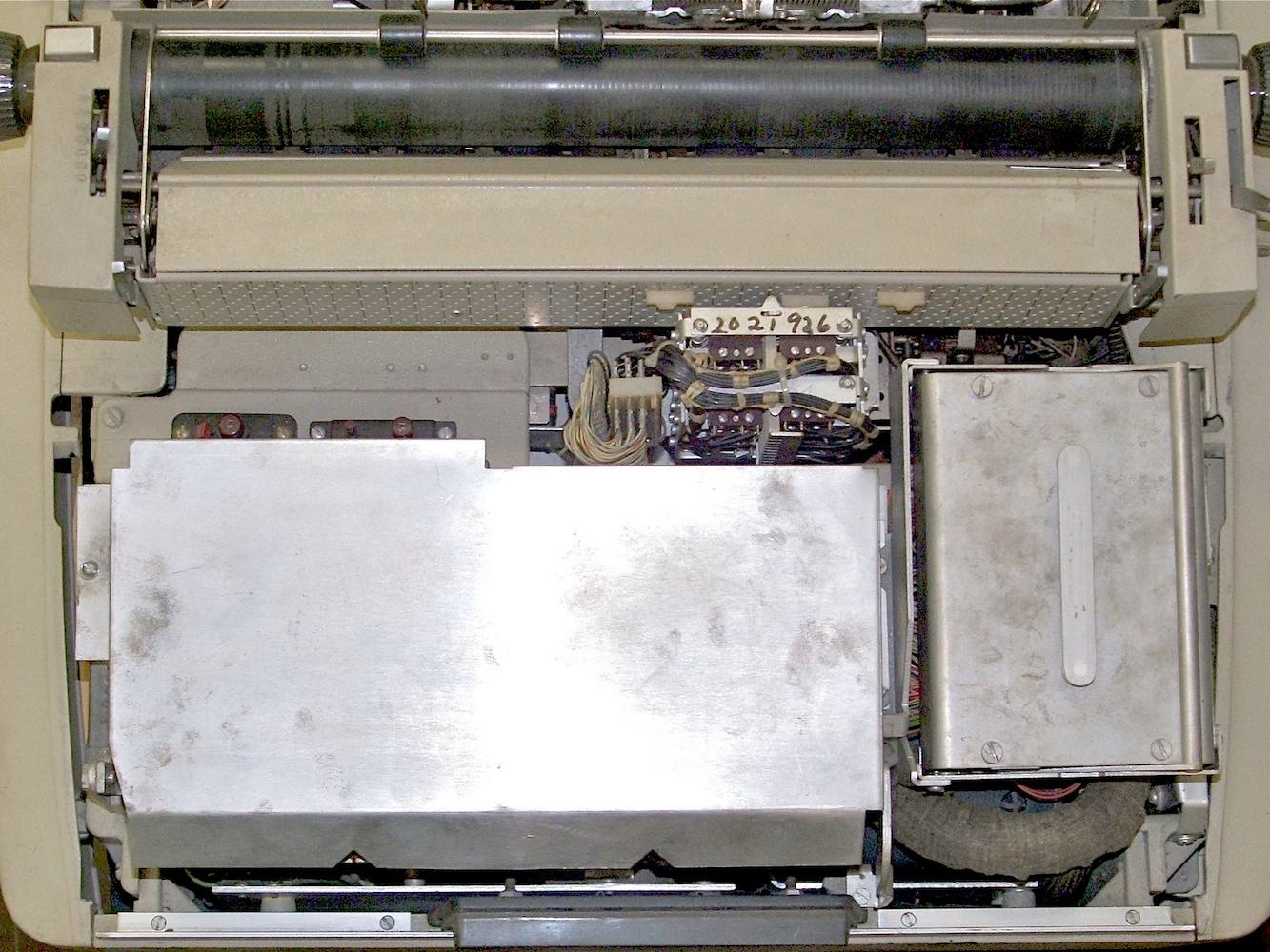
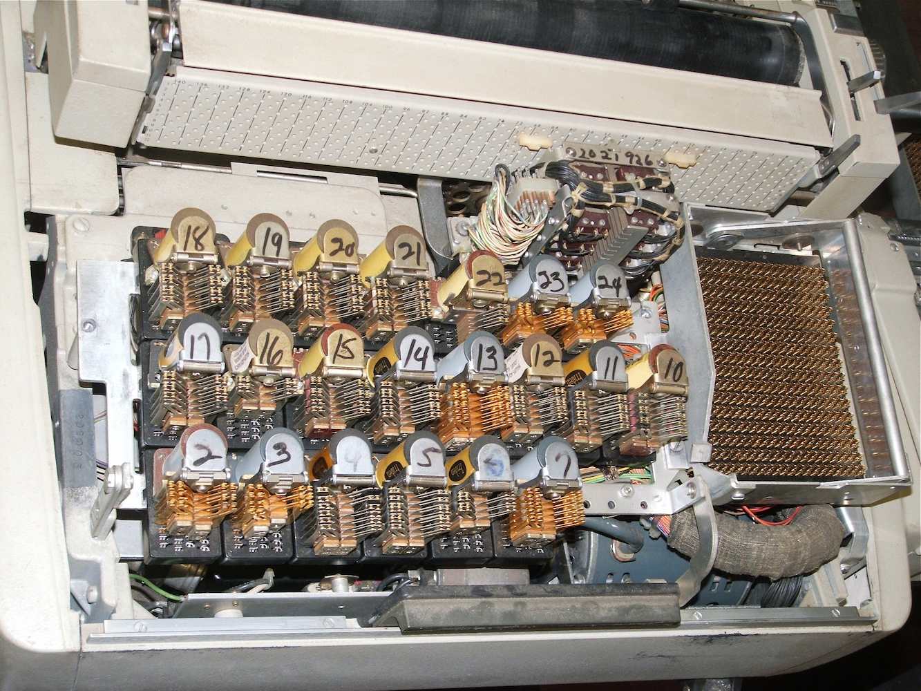
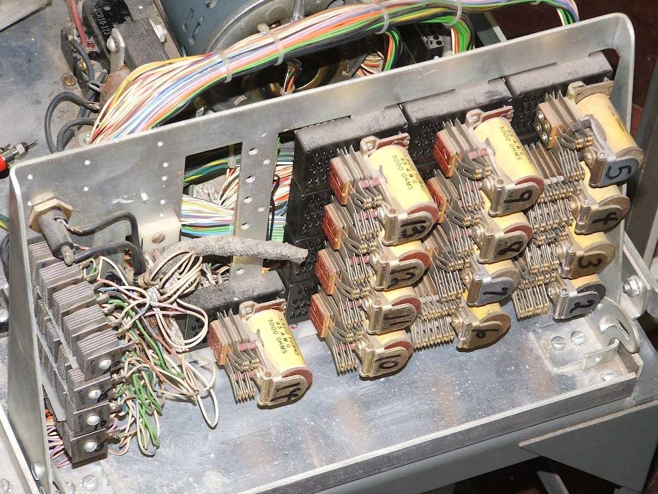
| The relays and plugboard | |
|---|---|
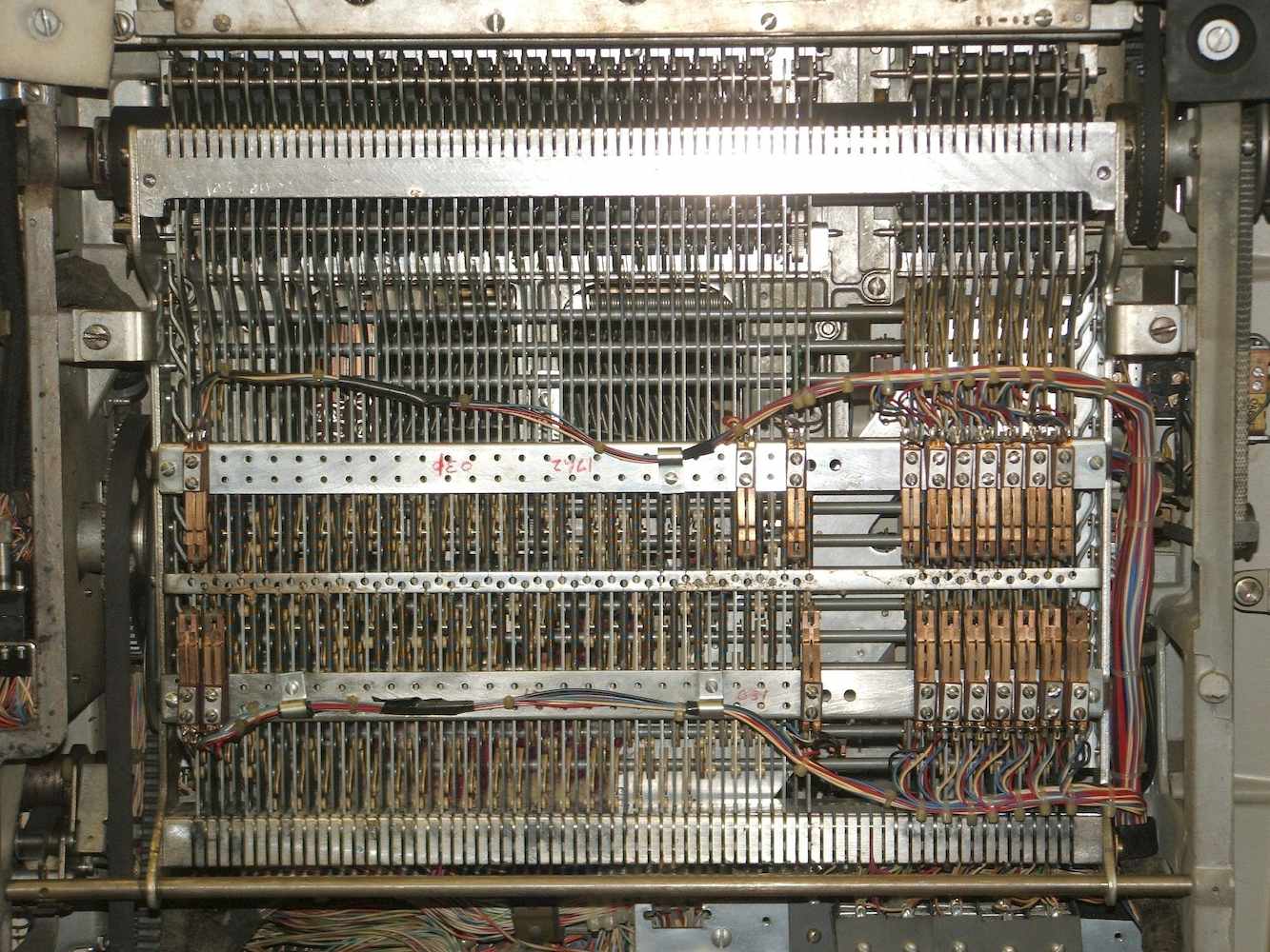
These relays, together with the plugboard, are the source of the trade-mark Programmatic that Friden applied to these mahchines. On recept of specific control codes, the machine could switch between reading from its main paper-tape reader, a an optional secondary reader, and the keyboard.
The plugboard socket has 320 contacts (16 rows by 20 columns), and the program
on the back of the plugboard takes the form of a dismaying tangle of wires.
The back of the plugboard has alphabetic row labels and numerical column
labels printed on it to aid the programmer, along with lines dividing the
different fields of contacts, but there is no explanation of the fields.
|
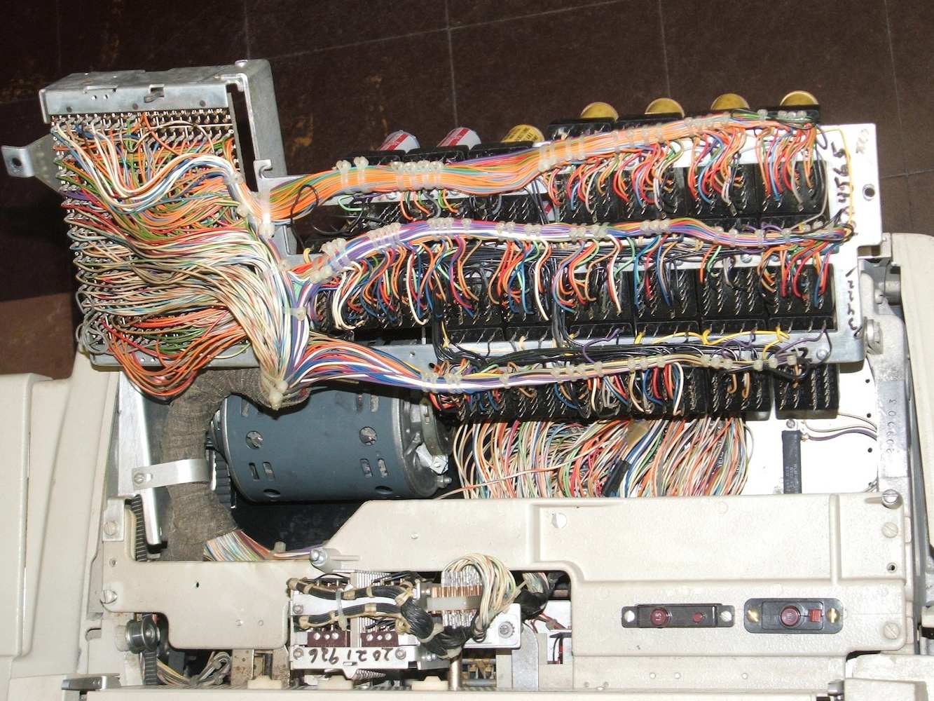
| The backplane |
|---|
|
|
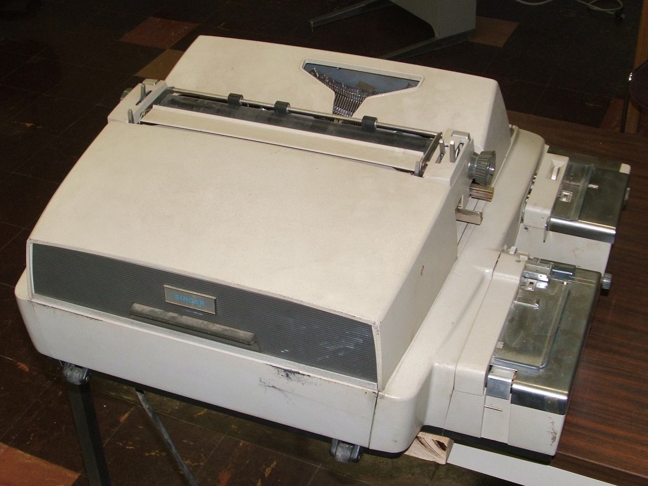
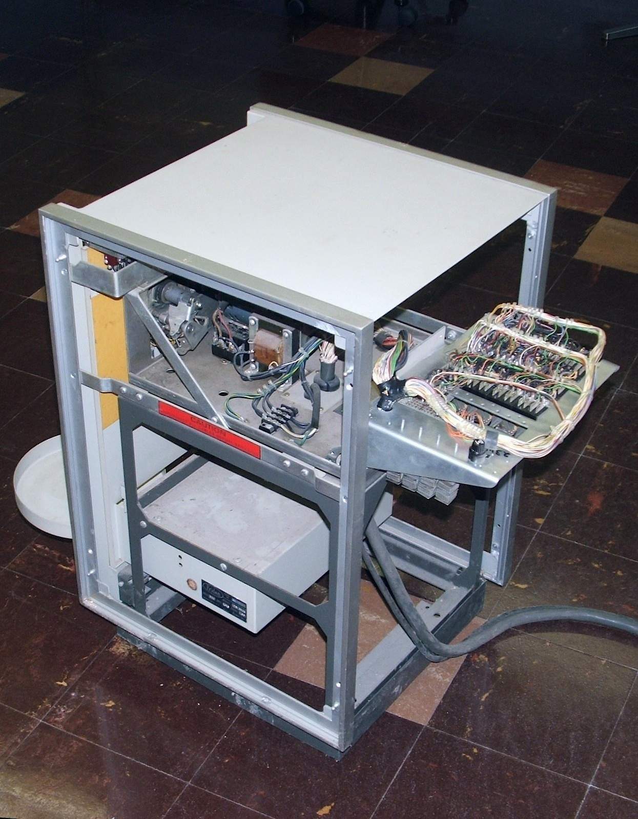
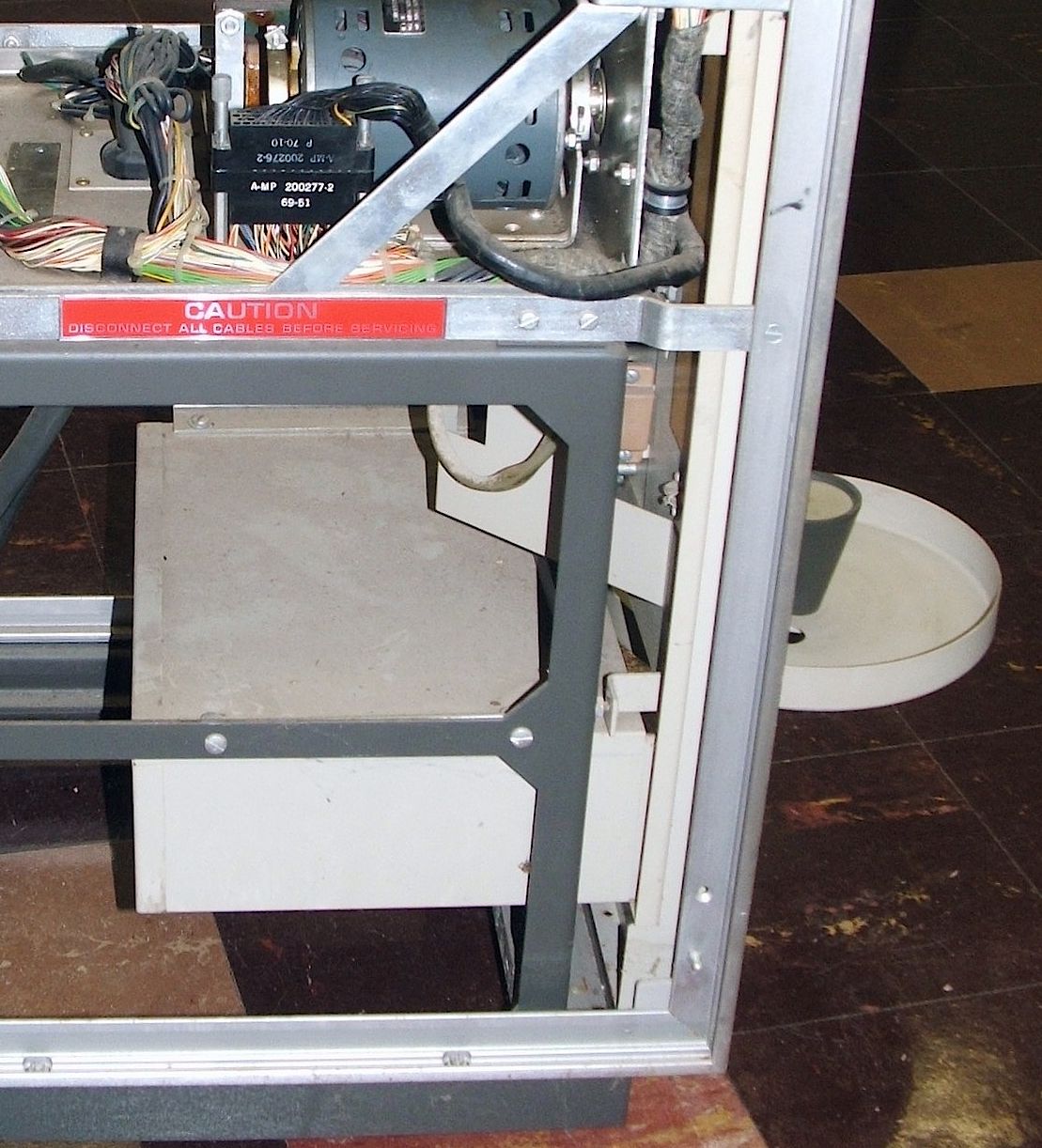
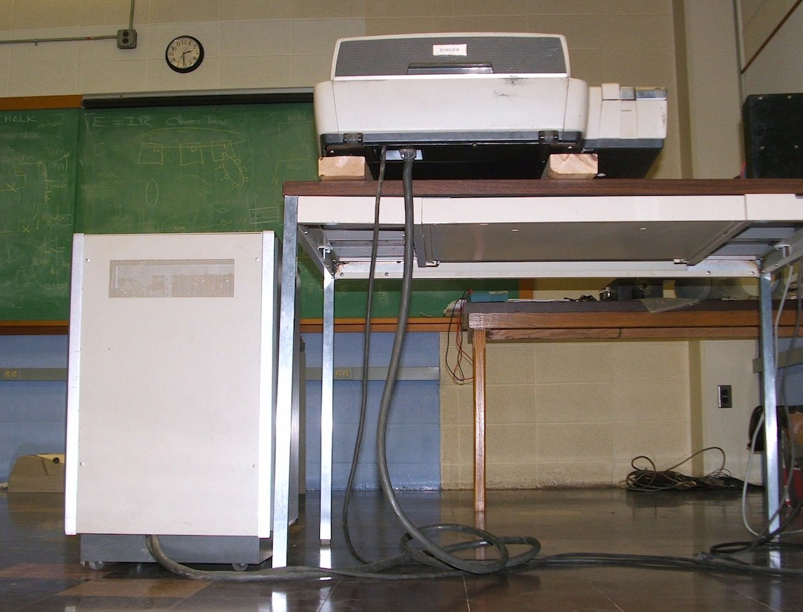
| 2314 front and with skins removed | |
|---|---|
The cabinet back is held on by quick-release screws -- loosen them and the latches on their back sides turn 90 degrees to release the back. The cabinet sides snap off (you need to push from inside to unsnap them). With the cabinet opened up, it looks like the entire structure of the cabinet is built around a smaller cabinet. Specifically, it looks suspiciously like the frame for the base of the unit shown in this undated brochure from the 1950s:
-- Friden Flexowriter with Selectadata
The actual reader mechanism appears identical to that on the older machine.
|
| |
| 2314 ID tag | |
|---|---|
The biggest puzzle on this tag is the advertised current draw of 1.51.8 Amps;
our best speculation is that there was no room for a space, and that this
really should be read as 1.5 1.8.
Judging by the more complete data on the motor nameplate (see next section),
these two current ratings apply at 60Hz and 50Hz respectively.
The space in the middle of the
model number poses a second puzzle; it appears to be another accident.
| |
| 2314 date codes | |
|---|---|
Note that the Computer History Museum has a Model 2214 Selectadata. The photo they posted and the physical description of their machine suggest that it is identical to this one.
Another physically similar machine was the 2212 Auxiliary Paper-Tape Reader, mentioned on the final page of this brochure:
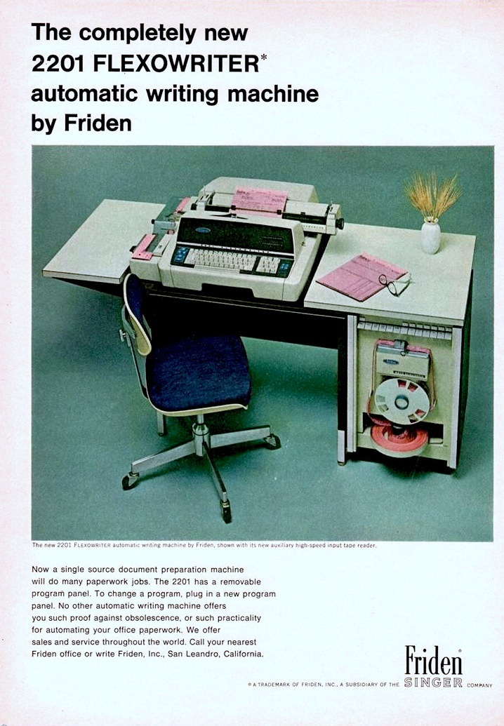
-- Entirely New 2201 Flexowriter Automatic Writing Machine by Friden
|
|
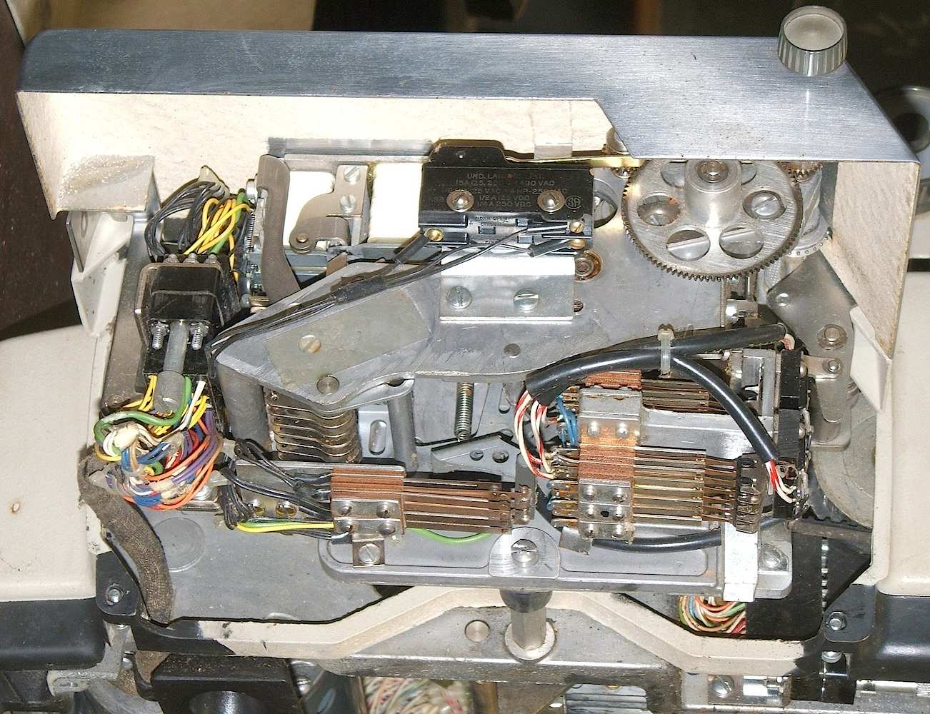
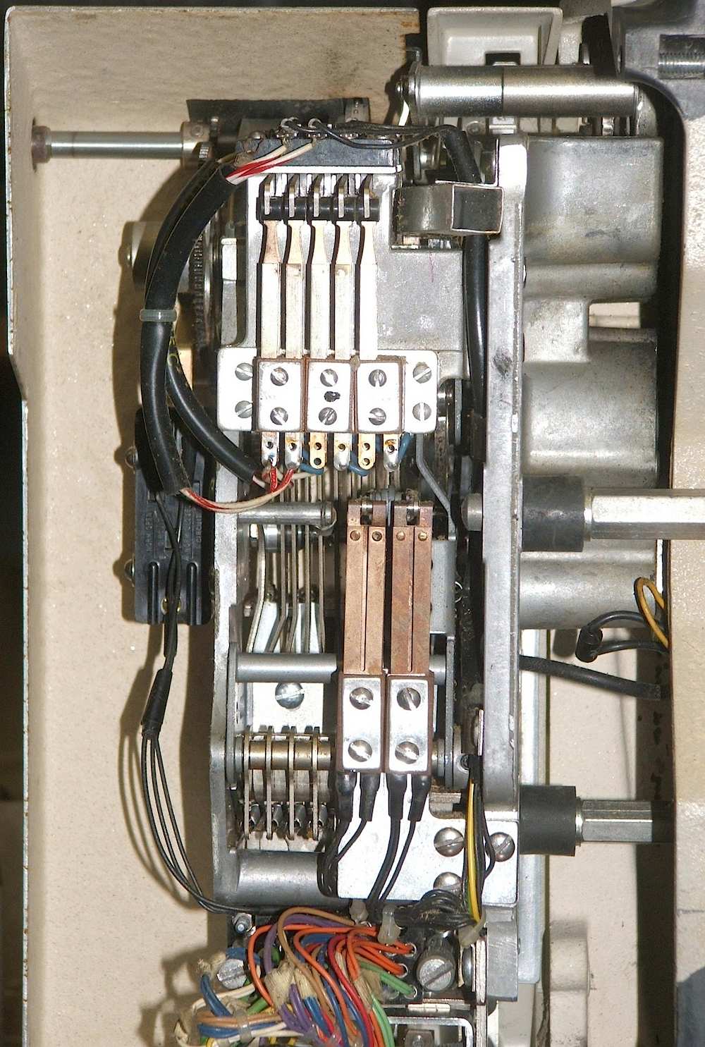
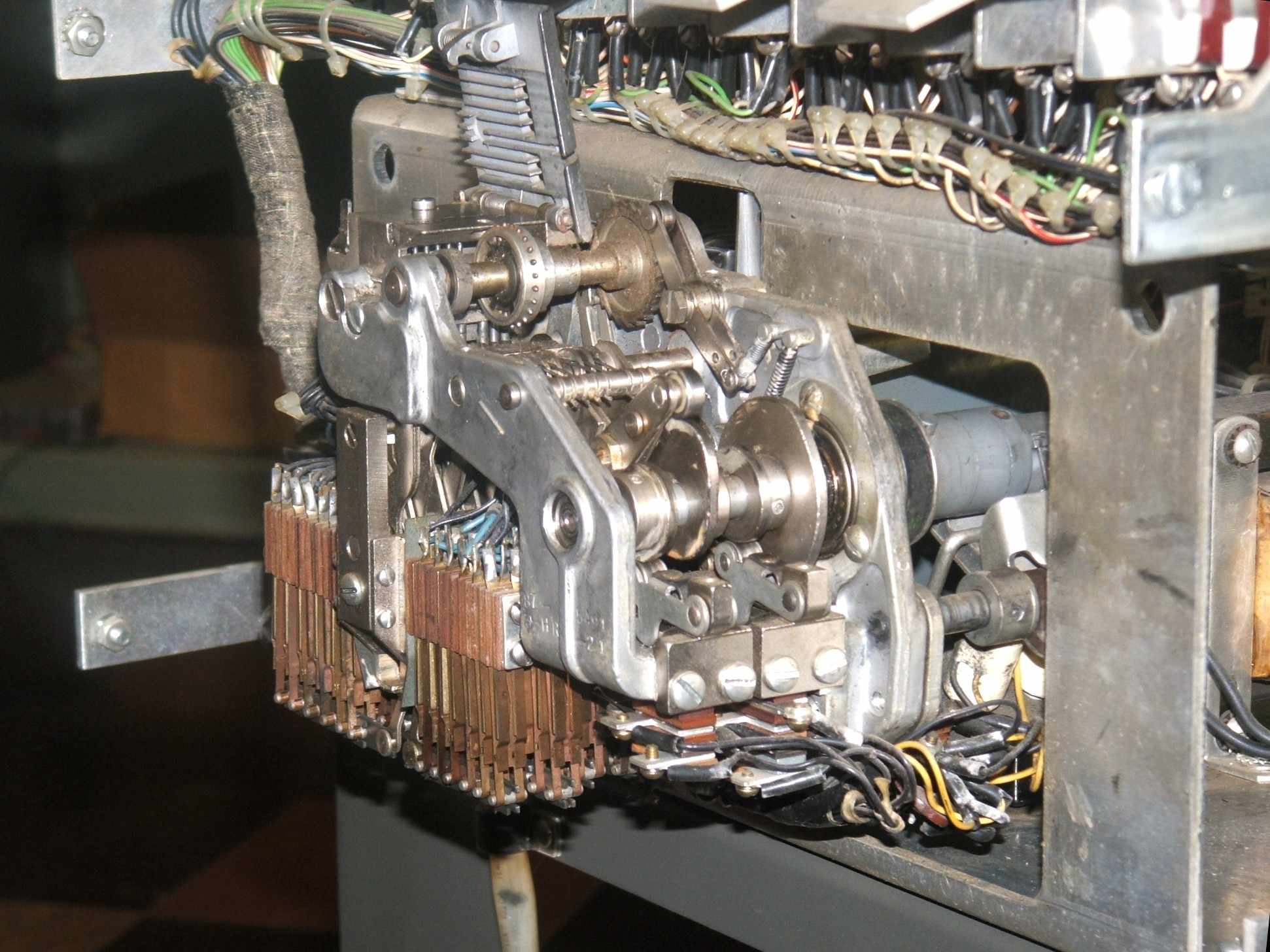
| Reader front and rear views | |
|---|---|
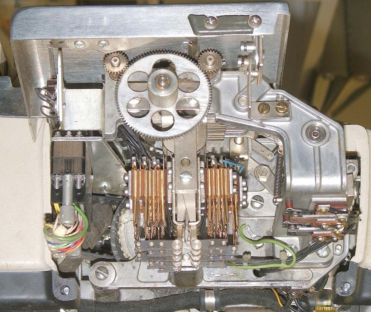
The clutch drives a camshaft on the front right side of the reader. The cams
on this shaft work the pawls that advance the tape feed sprocket, and they work the levers that raise and lower the pins that sense the characters encoded on
the 8 data tracks of the paper tape. The bottom end of each sense pin controls
a bank of switches.
|
| |
| 2314 Motor ID plate | |
|---|---|
While the mounting cabinet differs considerably, the drawings in this U.S. patent seem to agree with the operation of our reader. Figures 4 through 7 document the wrap-spring clutch, while Figures 14 through 17 show how the reader operates.
-- 2927158 Code-Form Converter, Edwin Blodgett, 1960.
|
|
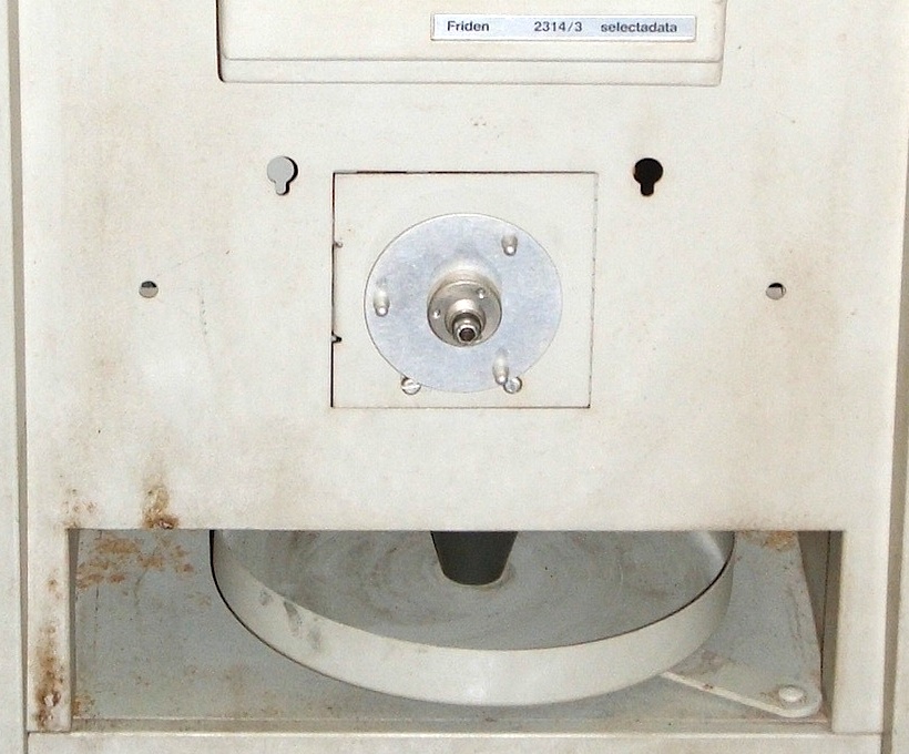
| Front and side view | |
|---|---|
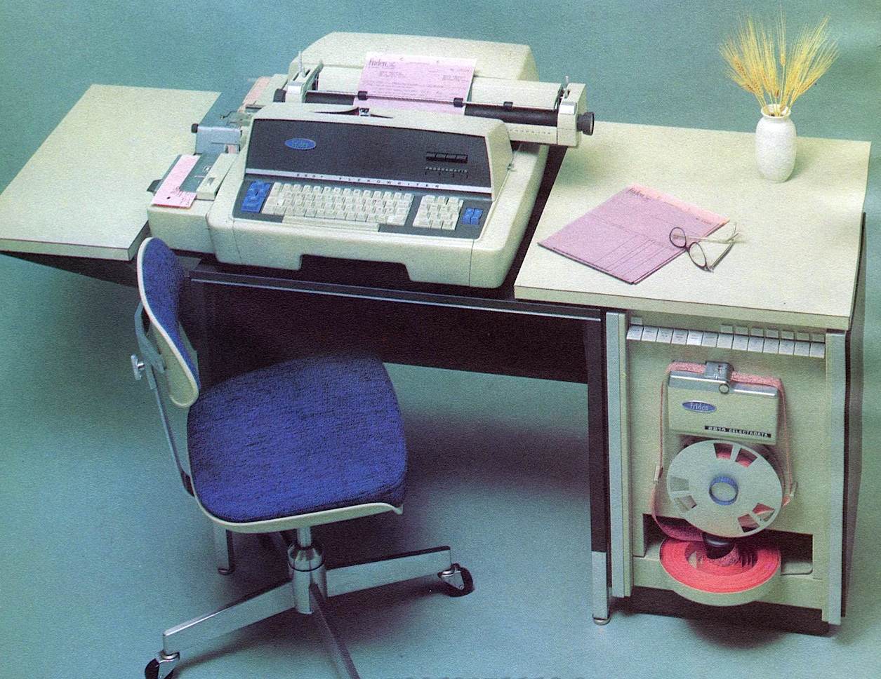
The supply tray itself spins very freely, particularly after we lightly oiled its pivot. The center knob is conical, and in the photo in the section on The Table, you can see that the tape feeds from the center of the spool, guided up out of the center on the conical side of the knob and then curving up over the edge of the cubby to continue up the face of the machine to the tape reader. The paint on the left side of the top edge of the cubby of our machne is worn exactly where the tape in the photo of the table would rub.
We are missing the take-up reel, but the take up reel hub is clearly visible in the face view above. The hub is driven through a simple slip clutch by a small squirrel-cage motor behind the front. Once oiled, it provided uniform light tension on the hub when turned on. The hub has 3 snap connectors that evidently connected to a removable take-up reel, to judge by the photo in the section on The Table. The face of this reel could be removed from the back in order to remove the tape from the take up reel for storage or to place it in the feed tray for re-reading.
Note that the Computer History Museum has a pair of take-up reel covers. They have posted photos that make it clear that these are among the parts we are missing.
The take-up-reel hub and motor are mounted on a door that latches flush with
the cabinet front using a magnetic catch. This door opens inward to swing the
hub back just far enough that it clears the plane of the cabinet front.
Two holes in the cabinet front in line with the top of the door suggest that
some optional feature could be attached there, perhaps a shelf or bin for
feeding fanfold tape?
|
|
| The relay panel |
|---|
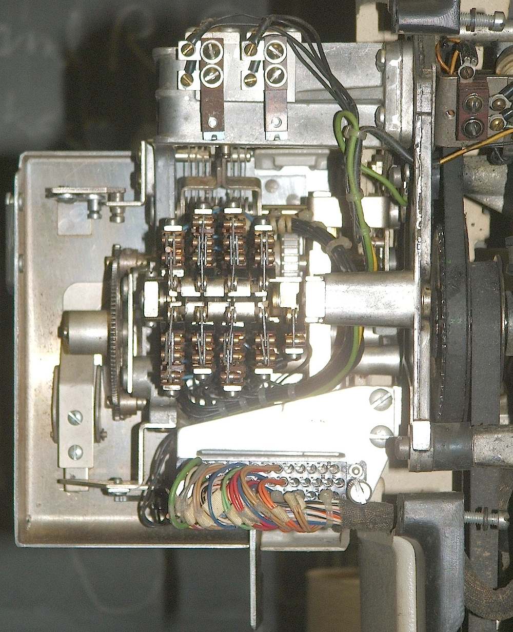
To the left of the relays (from the rear view) is a bank of 20 small
selenium rectifiers.
While it is difficult to trace the wires, it appears likely that
these are
flyback diodes
connected across the different relay and actuator coils in the machine
in order to suppress sparking on the relay and switch contacts powering those
coils.
|
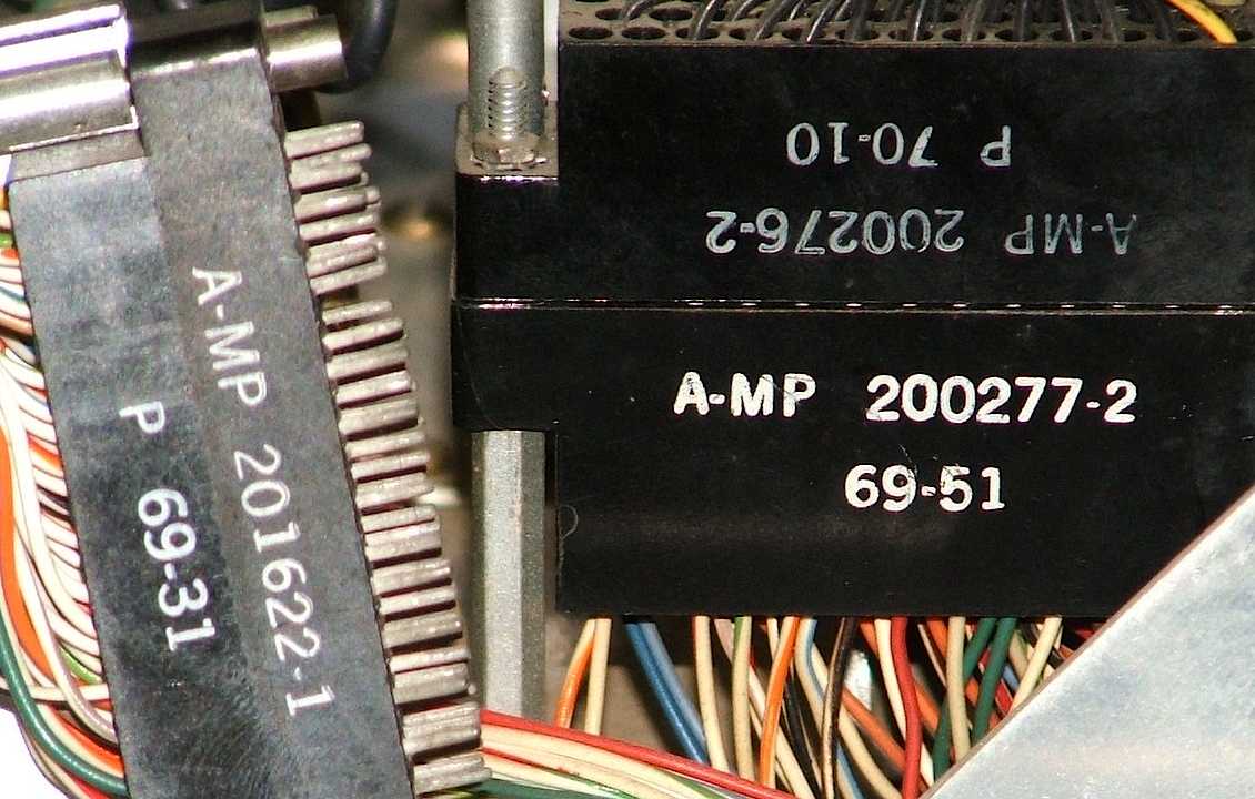
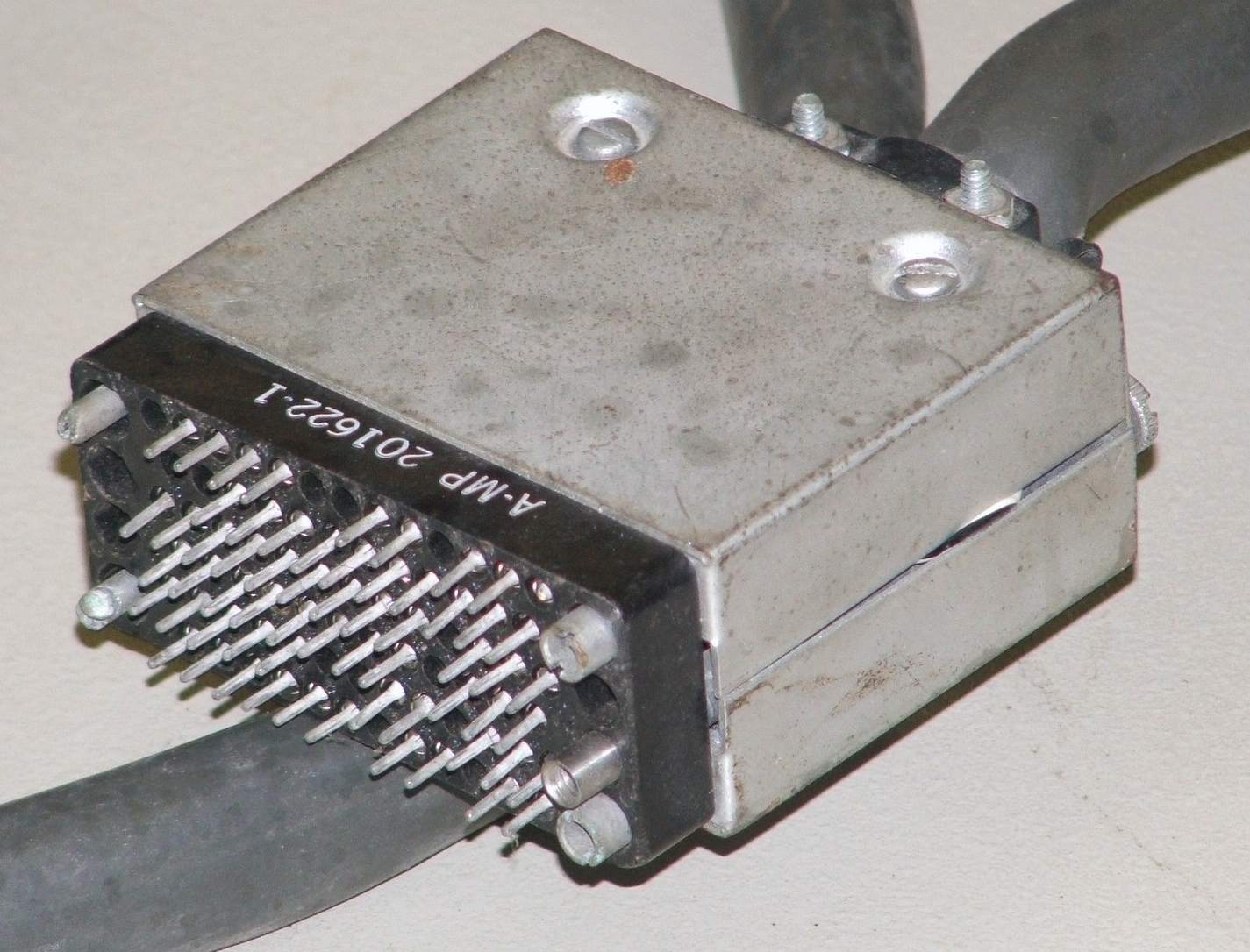
| The 75-pin plug |
|---|
Unfortunately, as we recieved it, one pin on the plug
(the upper right pin in the photo) is broken and one jack-screw on
the plug is missing its male insert (the left jack-screw in the photo).
The jack-screws have double-lead threads, meaning we cannot duplicate them with
commonly available taps and dies. Fortunately, the
manufacturer and part number are clearly stamped on the connector.
This led us on an interesting and eventually successful
search for replacement parts.
|
| Connecting the pieces |
|---|
After
repairing the plug.
at the end of the cable from the 2314 auxiliary punch,
we were able to plug the punch into the 2201 Flexowriter and begin testing.
Finally, typing on the keyboard made the typing mechanism work, except that
the carriage would not move side to side, nor the ribbon rise to meet the
type bars.
|
-- Entirely New 2201 Flexowriter Automatic Writing Machine by Friden
The same photo was used in this 1965 ad.
We have found another picture of the table on page 481 of the book Banking Automation: Data Processing Systems and Associated Equipment, Volume 1, edited by G. W. A. Dummer, F. P. Thomson, and J. Mackenzie Robertson, Pergamon Press, 1971. This photo shows the same table from the front left, with a center-feed paper-tape tray (identical to that at the bottom front of the 2314 auxiliary reader) mounted on the outside of the left leg of the table, about halfway to the floor, feeding a reel of tape into the paper-tape reader on the side of a Friden 2340. Two take-up reels (presumably motorized) and a tape-feed reel for the punch are also mounted on the left table leg.
One of the Flexowriters at the Computer History Museum, a Model 2301, includes the table we are missing. Their photos clearly show the motorized take-up reels for the paper-tape reader and punch on the left side of the table, as well as mounting holes below the reels where the center-feed tape reel holder and the tape supply reel for the punch can be mounted.
A similar table, although with
different legs, appears in this photo from the Rutherford Laboratories
Photographic collection, taken on June 3, 1969 showing
John Bailey, Oxford and New Zealand working at a Friden Flexowriter.